HapticWhirl — Build & Theory Guide
This page is a one-stop resource for constructing and operating the HapticWhirl: a kinesthetic haptic controller that harnesses the dynamic properties of a flywheel with dual axes of rotation. It covers all the essential files, code, and theory necessary to build your own gyroscope-based haptic device and will be updated as the project evolves.
The project is published in Sensors (MDPI), 2024.
Teensy-Gyro — Microcontroller code FARE-KE — Evaluation framework
3D Model
A fully-realised 3D model ready for 3D printing is available via Autodesk Fusion. Explore it below or download from the dropdown menu:
Understanding the Theory
If you are new to gyroscopes, this video introduces the output torques from a spinning flywheel:
For a more in-depth mathematical treatment:
Further details are covered in the MIT OCW Dynamics course (16.07), particularly from lecture 26 onwards.
HapticWhirl Modelling
HapticWhirl generates torque through two coupled mechanisms: a spinning flywheel and a two-axis gimbal. Understanding how they interact requires building up from first principles.
Momentum Wheel
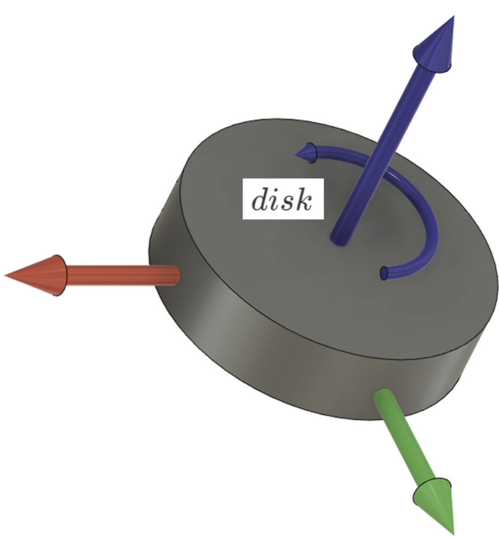
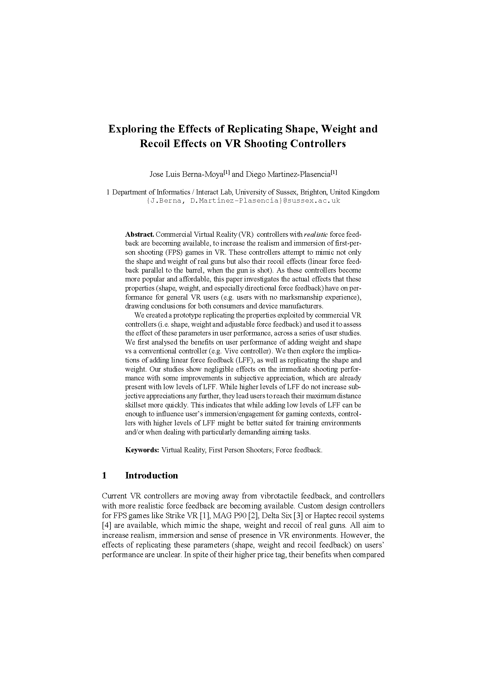
Figure — Momentum Wheel
The simplest case is a disk spinning about a fixed axis. When its spin rate changes, it produces a torque — the rotational form of Newton’s second law:
$$\tag{1} \vec{\tau} = \frac{d\vec{L}}{dt} = \mathbf{I}\,\dot{\vec{\omega}}^{\,\text{disk}}$$where $\vec{\tau}$ is the output torque, $\vec{L}$ is the angular momentum, $\mathbf{I}$ is the moment of inertia tensor, and $\dot{\vec{\omega}}^{\,\text{disk}}$ is the angular acceleration of the disk. Torque is proportional to how quickly the spin rate changes.
Steered Momentum Wheel
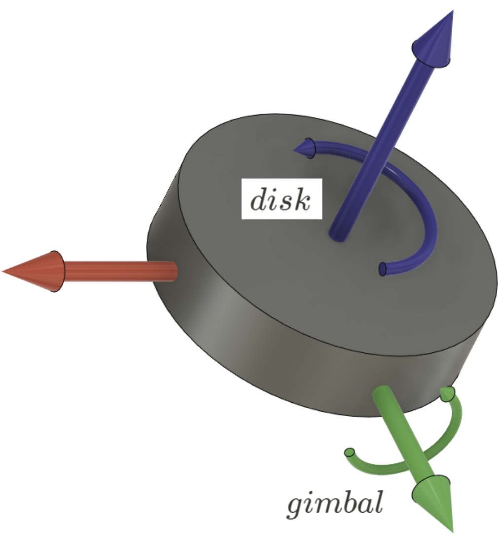
Figure — Steered Momentum Wheel
HapticWhirl uses a steered momentum wheel: the spinning disk is mounted on a gimbal that can tilt in two directions. This introduces a second source of torque — the gyroscopic effect. When the gimbal rotates, it continuously changes the direction of the disk’s angular momentum vector. That change in direction is itself a torque, even if the disk’s spin speed is constant:
$$\tag{2} \vec{\tau}_{\,\text{gyro}} = \vec{\omega}^{\,\text{gimbal}} \times \mathbf{I}\,\vec{\omega}^{\,\text{disk}}$$where $\vec{\omega}^{\,\text{gimbal}}$ is the angular velocity of the gimbal and $\mathbf{I}\,\vec{\omega}^{\,\text{disk}}$ is the angular momentum of the spinning disk.
Combining Equation 1 (disk angular acceleration) and Equation 2 (gyroscopic cross product) gives the total gyroscopic moment expressed in the disk’s reference frame $A$:
$$\tag{3} \vec{M}^{\,\text{gyro}}_A = \mathbf{I}\cdot\dot{\vec{\omega}}^{\,\text{Disk}}_A \;+\; \vec{\omega}^{\,\text{Gimbal}}_A \times \left(\mathbf{I}\cdot\vec{\omega}^{\,\text{Disk}}_A\right)$$This is the Euler equation for a rotating rigid body and forms the foundation for all subsequent calculations.
Variables Definition
To expand Equation 3 we need to express all quantities in a common reference frame. The device is decomposed into four rigid bodies, each with its own coordinate frame. The origin of every frame is fixed at the disk’s centre of mass.
| Component | Frame | Rotation angle |
|---|---|---|
| disk (spin) | $A$ | $\rho$ |
| inner gimbal (pitch) | $B$ | $\theta$ |
| outer gimbal (yaw) | $C$ | $\psi$ |
| handle (user grip) | $D$ | — |
Because the disk is rigidly attached to the inner gimbal, frames $A$ and $B$ always share the same orientation.
Notation: a superscript identifies the body; a subscript identifies the reference frame in which the vector is expressed:
$$\vec{\omega}^{\,\text{body}}_{\text{frame}}$$For example, $\vec{\omega}^{\,\text{outer}}_A$ is the angular velocity of the outer gimbal expressed in frame $A$.
Figure: Coordinate frames of the HapticWhirl kinematic model
In Equation 3:
- $\vec{\omega}^{\,\text{Gimbal}}_A$ — combined angular velocity of both gimbals (inner + outer), expressed in frame $A$
- $\vec{\omega}^{\,\text{Disk}}_A$ — total angular velocity of the disk (its own spin plus the motion carried to it by both gimbals), expressed in frame $A$
Angular Velocity of the Disk ($\vec{\omega}^{\,\text{Disk}}_A$)
The disk’s total angular velocity in frame $A$ is the sum of three independent contributions: its own spin, the inner gimbal’s pitch, and the outer gimbal’s yaw:
$$\vec{\omega}^{\,\text{Disk}}_A = \vec{\omega}^{\,\text{disk}}_A + \vec{\omega}^{\,\text{inner}}_A + \vec{\omega}^{\,\text{outer}}_A$$Each component is originally expressed in its own local frame and must be rotated into frame $A$ using a rotation matrix:
$$\vec{\omega}^{\,\text{Disk}}_A = \begin{pmatrix}0\\ 0\\ \dot{\rho}\end{pmatrix} + R_{B \rightarrow A}\begin{pmatrix}0\\ \dot{\theta}\\ 0\end{pmatrix} + R_{C \rightarrow A}\begin{pmatrix}0\\ 0\\ \dot{\psi}\end{pmatrix}$$The disk spins about its own $z$-axis at rate $\dot{\rho}$. The inner gimbal pitches about its $y$-axis at rate $\dot{\theta}$. The outer gimbal yaws at rate $\dot{\psi}$ about the $z$-axis of frame $C$.
Since $A$ and $B$ share the same orientation, $R_{B \rightarrow A}$ is the identity matrix. The outer gimbal (frame $C$) is related to frame $A$ by a rotation of $\theta$ about the $y$-axis:
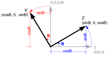
Figure: Rotation about the Y-axis — rotation matrix $R_{C \rightarrow A}$
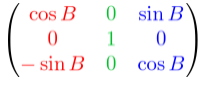
Figure: Rotation matrices and angular velocity vectors
Substituting the rotation matrices and evaluating:
$$\vec{\omega}^{\,\text{Disk}}_A = \begin{pmatrix}0\\ 0\\ \dot{\rho}\end{pmatrix} + \begin{pmatrix}1&0&0\\0&1&0\\0&0&1\end{pmatrix} \begin{pmatrix}0\\ \dot{\theta}\\ 0\end{pmatrix} + \begin{pmatrix}\cos\theta & 0 & -\sin\theta \\ 0 & 1 & 0 \\ \sin\theta & 0 & \cos\theta\end{pmatrix} \begin{pmatrix}0\\ 0\\ \dot{\psi}\end{pmatrix}$$After multiplying out and collecting terms:
$$\tag{4} \vec{\omega}^{\,\text{Disk}}_A = \begin{pmatrix}-\dot{\psi}\sin\theta \\ \dot{\theta} \\ \dot{\rho} + \dot{\psi}\cos\theta\end{pmatrix}$$Notice the coupling: the $x$ and $z$ components both involve $\dot{\psi}$ modulated by $\theta$. These mixed terms are the source of the gyroscopic torques.
Inertia Tensor of the Disk
The moment of inertia tensor quantifies how the disk resists angular acceleration — the rotational analogue of mass. For a symmetric disk it is diagonal:
$$\mathbf{I} = \begin{pmatrix}I_{xx}&0&0\\0&I_{yy}&0\\0&0&I_{zz}\end{pmatrix}$$
Figure: Moments of inertia for symmetrical objects
For a thin disk of mass $M$ and radius $R$:
$$\tag{5} \mathbf{I} = \begin{pmatrix}\tfrac{1}{4}MR^2 & 0 & 0 \\ 0 & \tfrac{1}{4}MR^2 & 0 \\ 0 & 0 & \tfrac{1}{2}MR^2\end{pmatrix}$$The moment about the spin axis ($z$) is twice that about the transverse axes ($x$, $y$), reflecting the disk’s rotational symmetry. The larger $I_{zz}$ means the disk stores angular momentum predominantly along its spin axis — exactly what produces the strong gyroscopic effect.
Angular Velocity of the Gimbal ($\vec{\omega}^{\,\text{Gimbal}}_A$)
The combined gimbal velocity in frame $A$ — needed for the cross product in Equation 3 — is the sum of the inner and outer gimbal contributions, each rotated into frame $A$:
$$\vec{\omega}^{\,\text{Gimbal}}_A = R_{B \rightarrow A}\begin{pmatrix}0\\ \dot{\theta}\\ 0\end{pmatrix} + R_{C \rightarrow A}\begin{pmatrix}0\\ 0\\ \dot{\psi}\end{pmatrix}$$Applying the same rotation matrices as above:
$$\tag{6} \vec{\omega}^{\,\text{Gimbal}}_A = \begin{pmatrix}-\dot{\psi}\sin\theta\\ \dot{\theta} \\ \dot{\psi}\cos\theta\end{pmatrix}$$Comparing with Equation 4, the gimbal velocity is simply the disk’s total velocity minus the disk’s own spin: $\vec{\omega}^{\,\text{Gimbal}}_A = \vec{\omega}^{\,\text{Disk}}_A - (0,\;0,\;\dot{\rho})^\top$. This makes intuitive sense — the disk inherits all gimbal motion and adds its own spin on top.
Angular Acceleration of the Disk ($\dot{\vec{\omega}}^{\,\text{Disk}}_A$)
Differentiating Equation 4 with respect to time, applying the chain rule to every product:
$$\tag{7} \dot{\vec{\omega}}^{\,\text{Disk}}_A = \begin{pmatrix}-\ddot{\psi}\sin\theta - \dot{\psi}\dot{\theta}\cos\theta\\ \ddot{\theta} \\ \ddot{\rho} + \ddot{\psi}\cos\theta - \dot{\psi}\dot{\theta}\sin\theta\end{pmatrix}$$The extra $\dot{\psi}\dot{\theta}$ terms arise from differentiating the product of two time-varying angles. They encode how simultaneously changing the gimbal’s pitch and yaw produces additional disk acceleration.
Computing Gyroscopic Torque
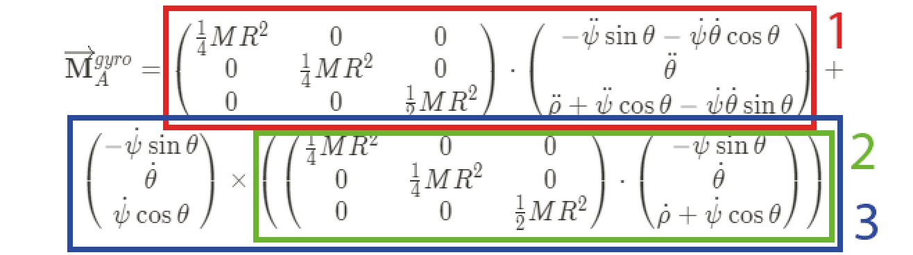
We now substitute Equations 5, 6, and 7 into Equation 3. The full expression for the gyroscopic moment is:
$$\tag{8} \vec{M}^{\,\text{gyro}}_A = \begin{pmatrix}\tfrac{1}{4}MR^2&0&0\\0&\tfrac{1}{4}MR^2&0\\0&0&\tfrac{1}{2}MR^2\end{pmatrix} \begin{pmatrix}-\ddot{\psi}\sin\theta - \dot{\psi}\dot{\theta}\cos\theta \\ \ddot{\theta} \\ \ddot{\rho}+\ddot{\psi}\cos\theta-\dot{\psi}\dot{\theta}\sin\theta\end{pmatrix} + \begin{pmatrix}-\dot{\psi}\sin\theta \\ \dot{\theta} \\ \dot{\psi}\cos\theta\end{pmatrix} \times\left( \begin{pmatrix}\tfrac{1}{4}MR^2&0&0\\0&\tfrac{1}{4}MR^2&0\\0&0&\tfrac{1}{2}MR^2\end{pmatrix} \begin{pmatrix}-\dot{\psi}\sin\theta \\ \dot{\theta} \\ \dot{\rho}+\dot{\psi}\cos\theta\end{pmatrix} \right)$$The first term is the inertial torque from the disk accelerating; the second is the gyroscopic torque from redirecting the disk’s angular momentum. Evaluating the cross product and collecting terms:
Substituting $I_x = I_y = \tfrac{1}{4}MR^2$ and $I_z = \tfrac{1}{2}MR^2$ and simplifying, the final gyroscopic moment in frame $A$ is:
$$\tag{9} \vec{M}^{\,\text{gyro}}_A = \begin{pmatrix} \tfrac{1}{4}MR^2\!\left(2\dot{\theta}\dot{\rho} - \ddot{\psi}\sin\theta\right) \\ \tfrac{1}{4}MR^2\!\left(\ddot{\theta} + \dot{\psi}\sin\theta\left(2\dot{\rho}+\dot{\psi}\cos\theta\right)\right) \\ \tfrac{1}{2}MR^2\!\left(\ddot{\rho} + \ddot{\psi}\cos\theta - \dot{\theta}\dot{\psi}\sin\theta\right) \end{pmatrix}$$Each row gives the torque about one axis of frame $A$. The coupling between $\dot{\rho}$, $\dot{\theta}$, and $\dot{\psi}$ is the essence of the gyroscopic effect.
Torque Applied on the Handle
Equation 9 expresses the moment in frame $A$ (the disk’s frame). The user grasps the handle at frame $D$, so the torque vector must be rotated into $D$:
$$\vec{M}^{\,\text{gyro}}_D = R_{A \rightarrow D}\cdot\vec{M}^{\,\text{gyro}}_A$$This is achieved in two sequential rotations, stepping through the intermediate frame $C$.
Step 1 — Frame $A$ → Frame $C$ (reverse the inner gimbal’s pitch $\theta$ about the $y$-axis):
$$R_{A \rightarrow C} = \begin{pmatrix}\cos\theta & 0 & \sin\theta \\ 0 & 1 & 0 \\ -\sin\theta & 0 & \cos\theta\end{pmatrix}$$
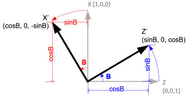
Figure: Rotation from frame A to frame D through intermediate frame C
Step 2 — Frame $C$ → Frame $D$ (reverse the outer gimbal’s yaw $\psi$ about the $z$-axis):
$$R_{C \rightarrow D} = \begin{pmatrix}\cos\psi & -\sin\psi & 0 \\ \sin\psi & \cos\psi & 0 \\ 0 & 0 & 1\end{pmatrix}$$
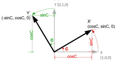
Figure: Rotation matrix for Z-axis transformation C→D
Multiplying the two matrices gives the combined rotation:
$$\tag{10} R_{A \rightarrow D} = R_{C \rightarrow D}\cdot R_{A \rightarrow C} = \begin{pmatrix}\cos\theta\cos\psi & -\sin\psi & \sin\theta\cos\psi \\ \cos\theta\sin\psi & \cos\psi & \sin\theta\sin\psi \\ -\sin\theta & 0 & \cos\theta\end{pmatrix}$$The torque felt at the handle is therefore:
$$\vec{M}^{\,\text{gyro}}_D = R_{A \rightarrow D}\cdot\vec{M}^{\,\text{gyro}}_A$$This vector is the haptic feedback the user experiences — the three-axis torque generated by the spinning flywheel and redirected to the hand through the gimbal mechanism.
Solving for Angular Accelerations ($\ddot{\theta},\;\ddot{\psi},\;\ddot{\rho}$)
In practice, the controller works in reverse: given a desired torque $\vec{M}^{\,\text{gyro}}_D$ and the current angular velocities, we solve for the angular accelerations needed to produce it. This is the inverse dynamics problem.
First, the desired torque is converted back from the handle frame to frame $A$ by applying the transpose of $R_{A \rightarrow D}$ (which equals its inverse, since rotation matrices are orthogonal):
$$\vec{M}^{\,\text{gyro}}_A = R_{A \rightarrow D}^{\,\top}\cdot\vec{M}^{\,\text{gyro}}_D$$Equation 9 then gives three scalar equations — one per axis — each of which can be rearranged to isolate one unknown angular acceleration.
Solving for $\ddot{\psi}$ (outer gimbal / yaw acceleration)
From the $x$-component of Eq. 9:
$$M^{\,\text{gyro}}_{A,x} = \tfrac{1}{4}MR^2\!\left(2\dot{\theta}\dot{\rho} - \ddot{\psi}\sin\theta\right)$$$$\ddot{\psi} = \frac{2\dot{\theta}\dot{\rho}}{\sin\theta} - \frac{4\,M^{\,\text{gyro}}_{A,x}}{MR^2\sin\theta}$$Alternatively, from the $z$-component (numerically preferable when $\sin\theta \approx 0$):
$$M^{\,\text{gyro}}_{A,z} = \tfrac{1}{2}MR^2\!\left(\ddot{\rho} + \ddot{\psi}\cos\theta - \dot{\theta}\dot{\psi}\sin\theta\right)$$$$\ddot{\psi} = \frac{2\,M^{\,\text{gyro}}_{A,z}}{MR^2\cos\theta} - \frac{\ddot{\rho}}{\cos\theta} + \dot{\theta}\dot{\psi}\tan\theta$$Solving for $\ddot{\theta}$ (inner gimbal / pitch acceleration)
From the $y$-component of Eq. 9:
$$M^{\,\text{gyro}}_{A,y} = \tfrac{1}{4}MR^2\!\left(\ddot{\theta} + \dot{\psi}\sin\theta\left(2\dot{\rho}+\dot{\psi}\cos\theta\right)\right)$$$$\ddot{\theta} = \frac{4\,M^{\,\text{gyro}}_{A,y}}{MR^2} - \dot{\psi}\sin\theta\left(2\dot{\rho}+\dot{\psi}\cos\theta\right)$$Solving for $\ddot{\rho}$ (disk spin acceleration)
From the $z$-component of Eq. 9:
$$\ddot{\rho} = \frac{2\,M^{\,\text{gyro}}_{A,z}}{MR^2} - \ddot{\psi}\cos\theta + \dot{\theta}\dot{\psi}\sin\theta$$These three equations form the control law for HapticWhirl: given the desired torques and the current state (angles and angular velocities), they specify the motor commands needed for the disk motor and the two gimbal actuators.